Vantage Pro 2 developments
2000 - Birth Davis Vantage Pro1
2003 - VP1 revision. T / H sensor now separate from ISS board
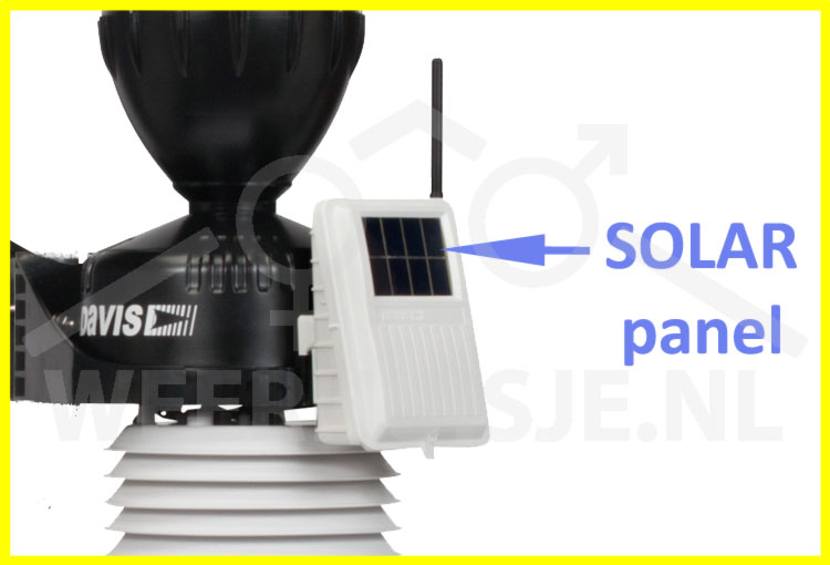
2005 - Introduction Vantage Pro2 (analogue T / H sensor - 7346.029)
2006 - Jan 1 and beyond: T / H sensor digital
2011 - 1-Aug. Introduction "green dot" data loggers. Dataloggers from before this date do not work with the newer stations.
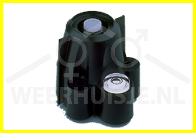
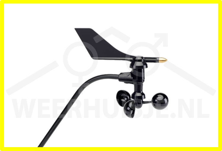
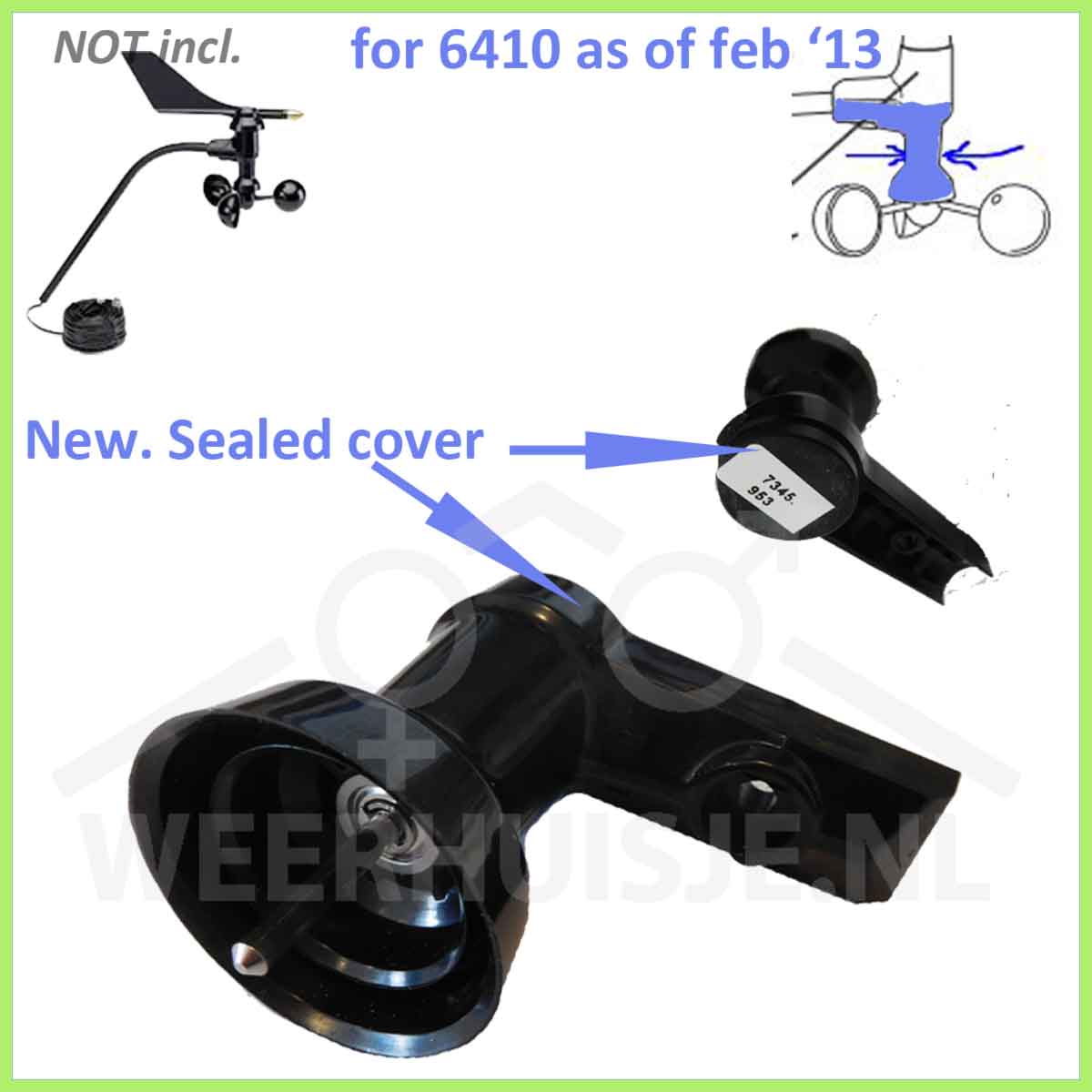
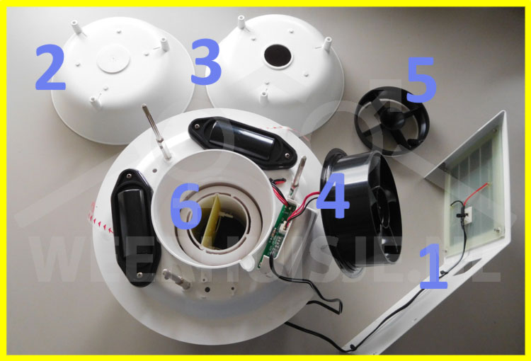
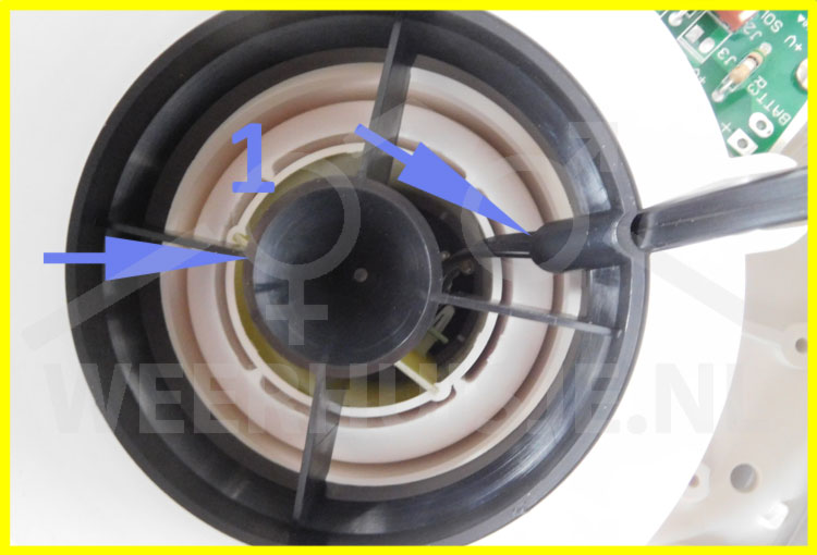
2013 - From Feb: new model (6410) anemometer, narrow neck and D-type wind vane. Replace switch with solid state sensor (electronic switch). Magnet now in (replaceable) windspeed cartridge instead of in wind cups.
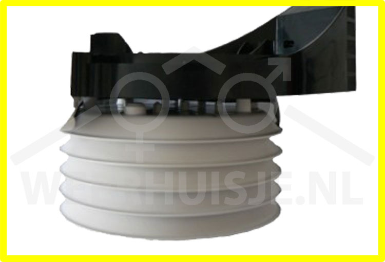
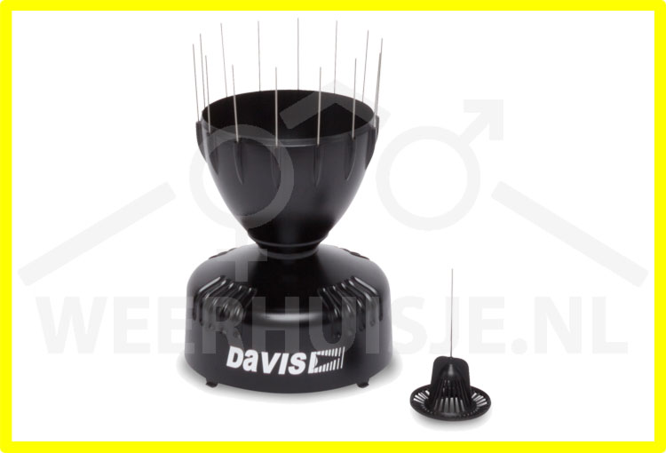
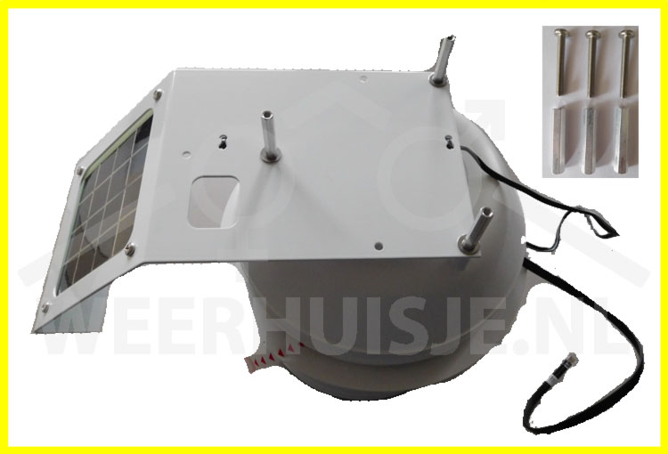
2014 - Improved rain cone with finger "grips", bird spikes and new dirt filter.
2016 - 1-Jan and beyond (mfg codeASxxx and higher): T / H sensor accuracy 0.3 ° C - 7346.070
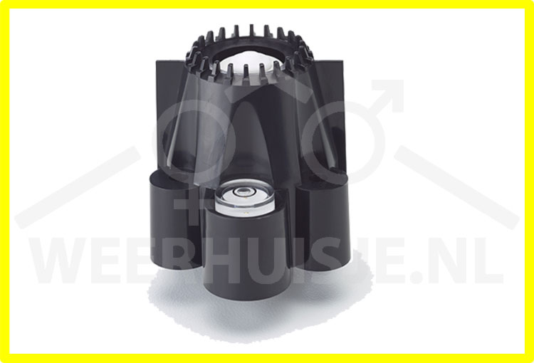
2017 - Jan 1 and beyond Aerocone rain cone. Aerodynamically shaped rain cone with dirt filter lock.
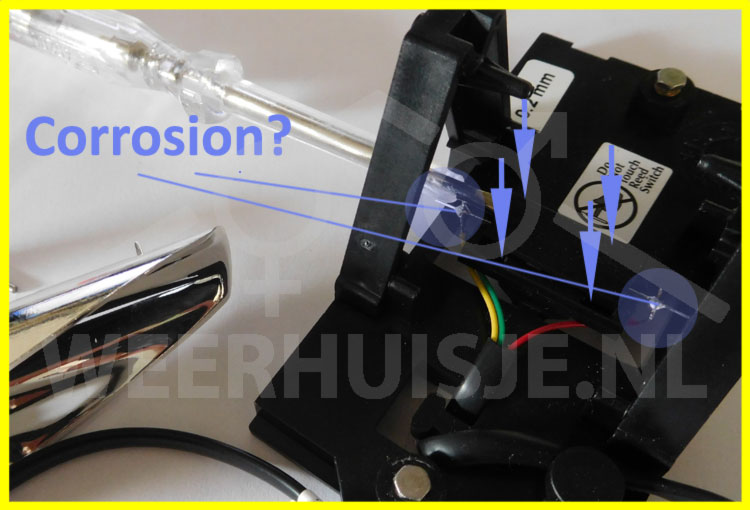
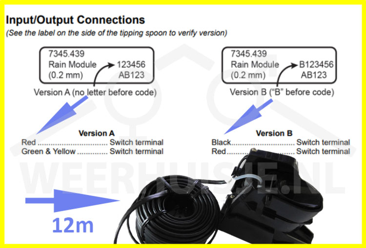
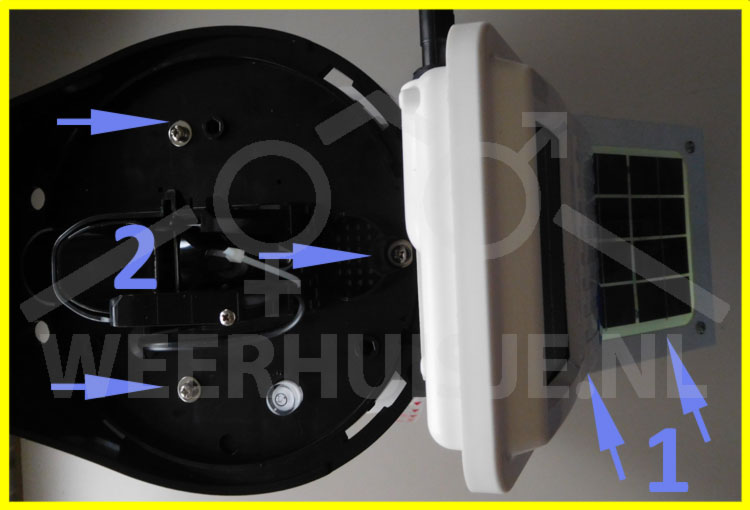
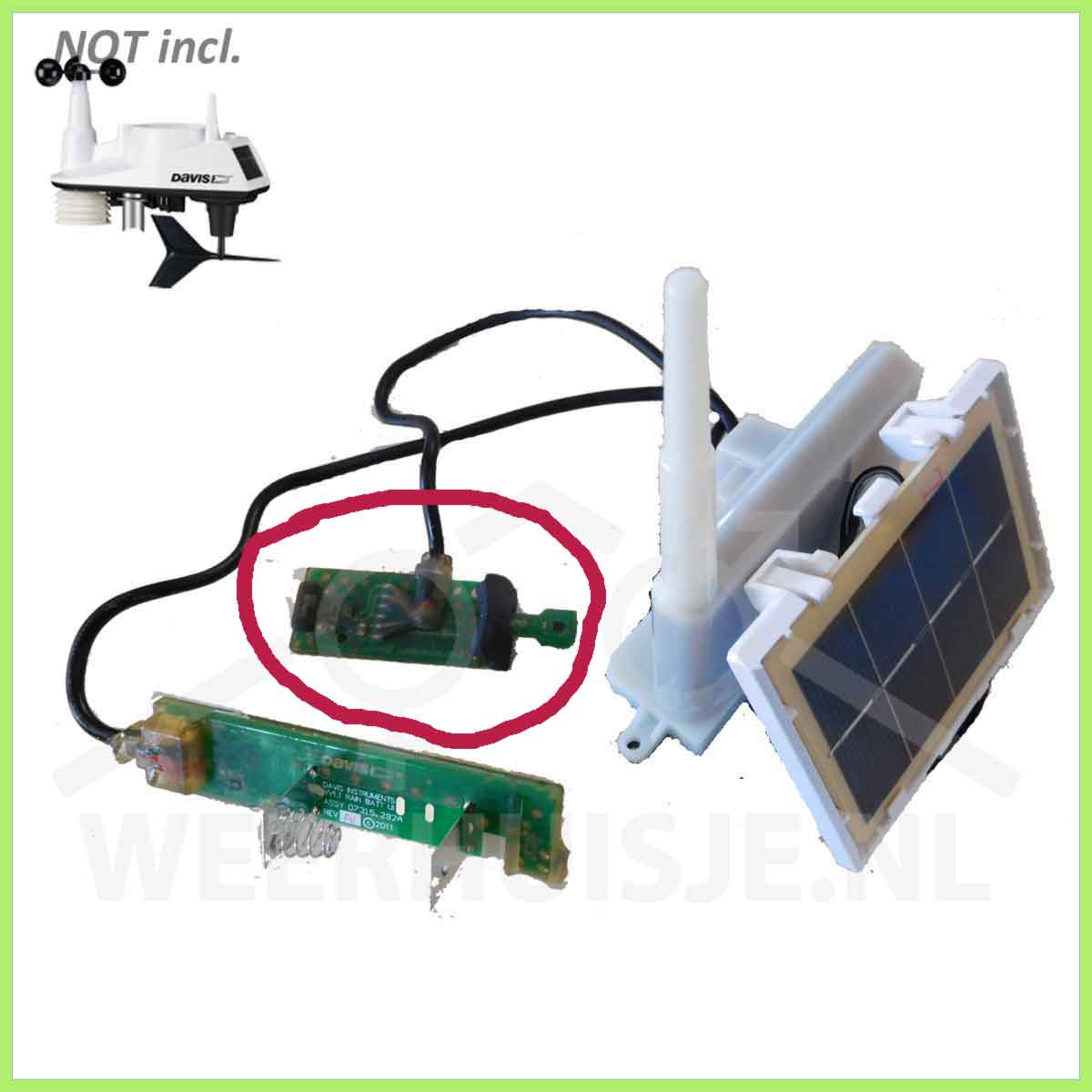
2019 - mid 2019 introduction of the single spoon rainn sensor with easy to replace reed switch.
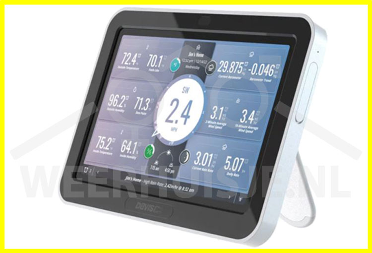
2023 - January release of the WeatherLink Console. The new color display for the Davis Vantage Vue and VP2 console. With local storage of historical data, having historical data available in graph form. The connection for a data logger is no longer present on the WeatherLink console
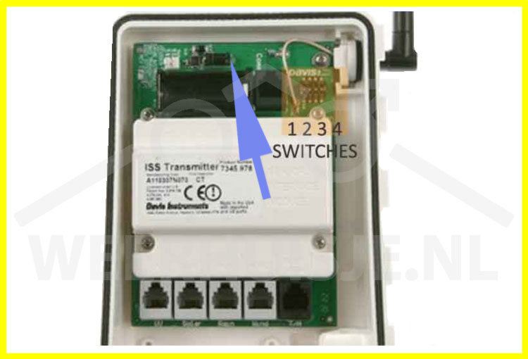
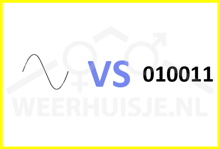
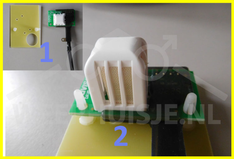
Analog VP2 (2004-2005) sensor vs new digital sensors.
The first Vantage Pro2 had an analog sensor (mfg code starting with A4 and A5). Later stations have a digital Thermo / hygro sensor.
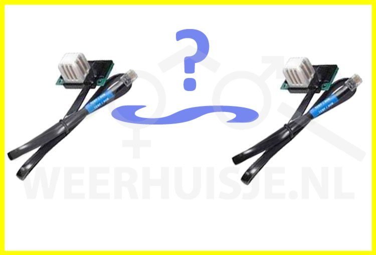
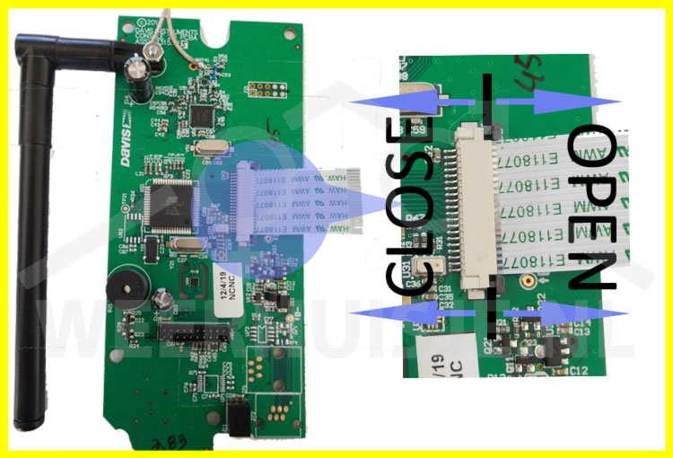
A Vantage Pro2 with analog sensor can be upgraded for use with the new digital sensors. For this, the transmitter board must be replaced by a recent version suitable for use with digital sensors.
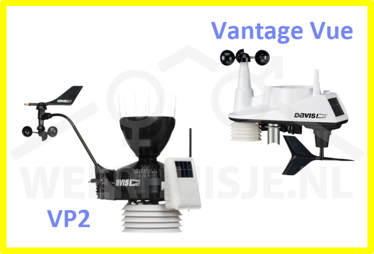
VP1 and VP2 interchangeable?
No - Console and ISS between VP1 (6310) and VP2 (6312) are not interchangeable.
No - Temp / hum sensors - see item: "Vantage Pro models from 2000"
Yes - Rain meter; anemometer; UV; Solar; Soil moisture; (Soil) temp; Leaf wetness
Yes - 6510xx, 6555 data loggers for consoles produced before 2012.
Note: The US and NON-US (OV - Over Seas) console / ISS parts are not interchangeable due to different transmission frequencies.
Determine the age of your station?
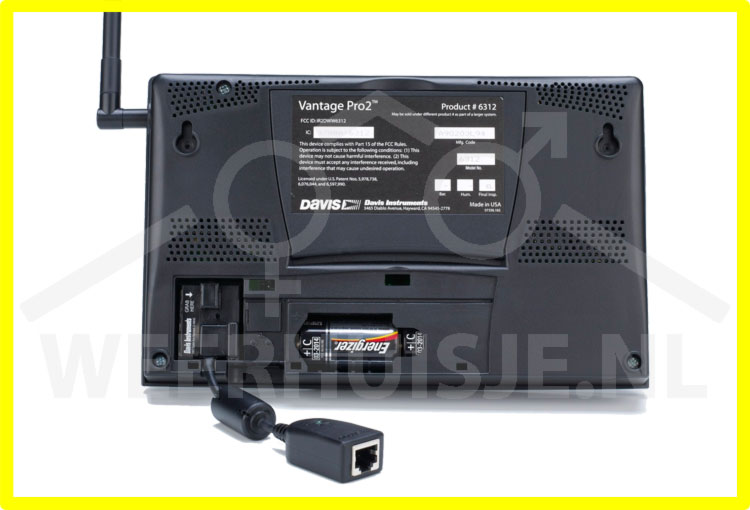
Decode first 6 digits of Mfg (bar) code on the back of the console to: YYMMDD.
I.e: Mfg code: AA111012P002> First 6 digits: 111012> years:(20)11; month:10 day:12. Console has been produced 12-10-2011
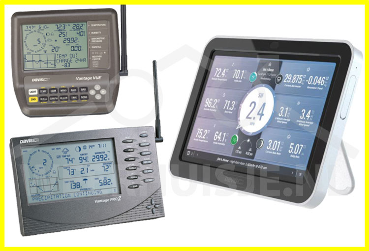
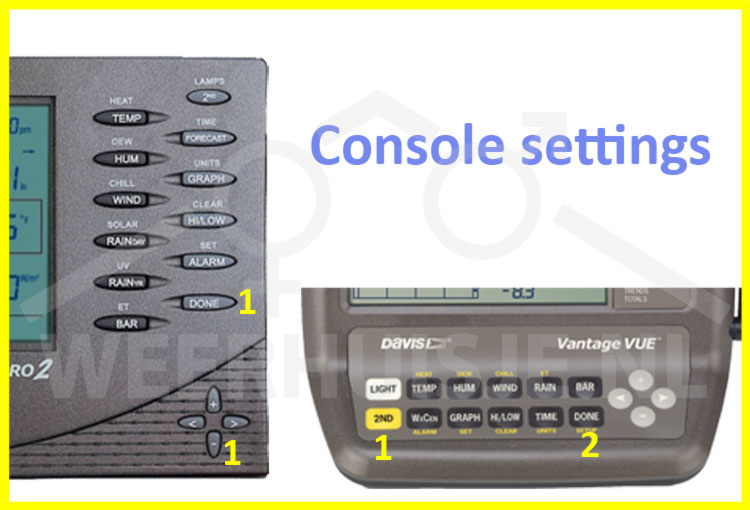
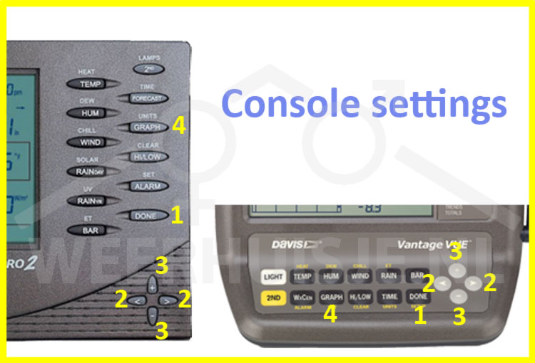
1.3 Consoles
2023 update: Introduction of the "Weatherlink console". for both the VP2 and Vantage Vue. with various display options such as real time, graphs, etc. Connects via WiFi to the Davis weatherlink weather site. Weatherlink console also has its own storage for several years of weather data storage.
Screen tip: The console has a protective foil with a cut off corner at the bottom right. Although the foil can be removed without any problems, Davis recommends leaving the protective film on the display.
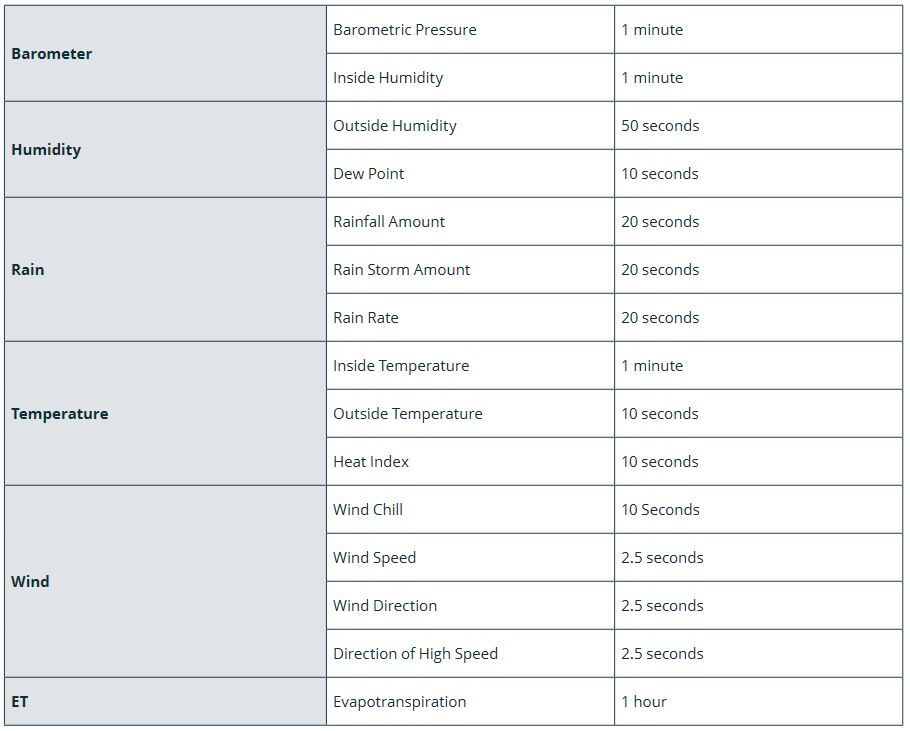
Both the Davis Vantage Pro2 and the Vantage Vue feature an extensive console with internal memory for storage of weather data. Every 2.5 seconds weather data is refreshed resulting in practically real time weather data.
You do have a view of the current situation at any time, especially for stormy situations and downpours. This way you are constantly on top of the weather! Furthermore, the console has a graph with last 24 hours data for all weather variables.
In addition, the highest / lowest values per day, month and year are displayed at the touch of a button. You will also receive notifications about phenomena such as annual meteorites, the transition to the summer, battery status, etc.
The internal display memory remembers all weather variables during the last 25 hours, 25 days, 25 months, and even 25 years of historic data of rain measurements. This data is also retained after a power failure (as well as all settings do).
The historical data is shown in a graph. You can easily view all individual values with corresponding times. The console furthermore accommodates the optional data logger for recording all weather data in detail. On both the Vantage Pro2 and the Vantage Vue display alarms can be set which emit a beep when the specified limit is exceeded.
The console is powered by the supplied power adapter. For backup in the event of a power failure, the console can be equipped with regular alkaline batteries.


 Nederlands